
Thanks for taking the Master Samurai Tech ASTI 2015 Quiz! You have been entered in the raffle, and sent an email that contains your answers.
ASTI 2015 SPECIAL: Enroll in any Samurai Tech Academy course by Mardi Gras (February 17) and receive a 15% discount! Simply use coupon code ASTI15 at checkout. You may use the code for multiple enrollments or courses!
We chose questions related to circuits, schematics, motors, and VFD systems for this ASTI quiz because this is one of the greatest strengths of the Samurai Tech Academy: explaining and demystifying circuits, reading schematics, troubleshooting with schematics, understanding motors, and being knowledgeable on modern technologies such as VFD systems.
Scroll down for the answers!
Question 1:
Simple Circuit Survey
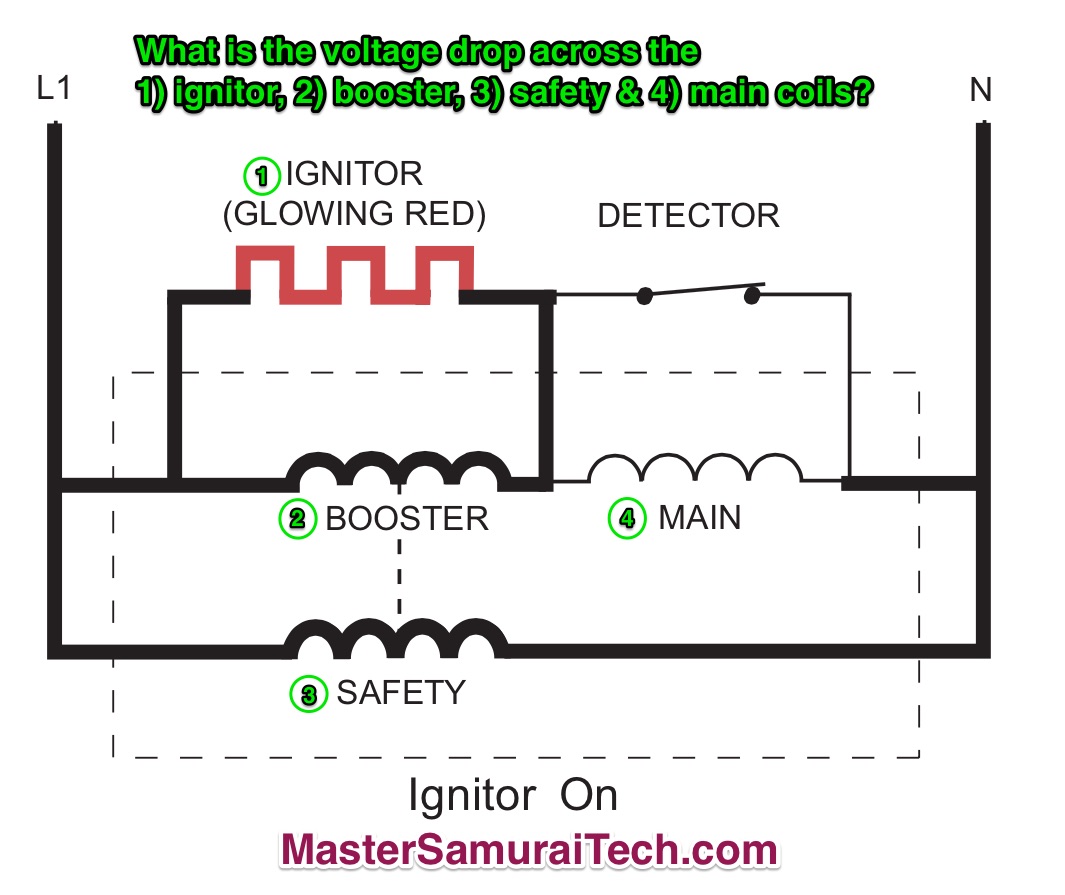
Start by noting the power supply. It’s called out as L1 to N. So we know that the power supply to this circuit is 120 VAC.
Ignore the thickness of the lines in the drawing; it doesn’t mean anything.
Since the ignitor is glowing, we know that 1) we have a valid power supply, and 2) current is flowing, so there will be a voltage drop across the ignitor (the load) and work is being done (producing heat).
Next, we note that the ignitor, booster, and safety are all in parallel with each other. From the Fundamentals of Appliance Repair training course, we know that the voltage in each parallel circuit is equal to the supply, in other words, 120 VAC in each leg. That’s just the way circuits work.
“But what about the voltage drop across the main coil— doesn’t that subtract from the voltage available to drop across the ignitor and booster?”
Ah, Grasshoppah, let’s look at that voltage drop across the main coil. Notice that the detector is closed. As such, it is shunting the current around the main coil because current will take the path of least resistance. Since there is no current flow through the main coil, the voltage drop across the main coil is effectively zero.
So the answers are:
1. Ignitor: 120 VAC
2. Booster: 120 VAC
3. Safety: 120 VAC
4. Main: 0 VAC
Question 2:
Dryer Schematic Quiz - Click for Larger View (opens in a new window)
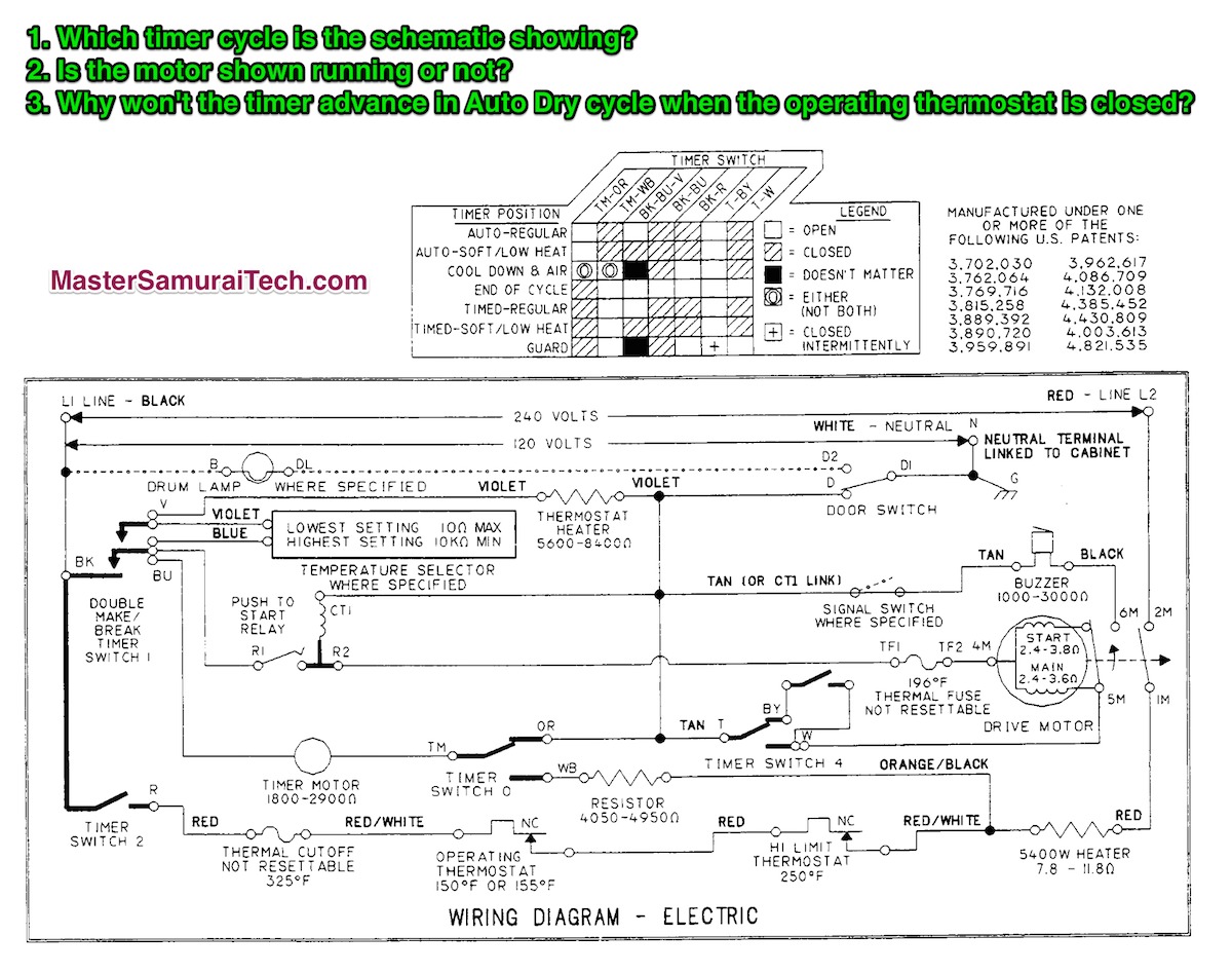
1. Which timer cycle is the schematic showing?
Looking at the timing chart, we see that the cycles on this dryer fall into two main groups: auto and timed. The big distinction between the two is timer contacts TM-OR (timed dry cycles) and TM-WB (auto dry cycles). Since the schematic shows that the TM-OR contacts are made, then we know we're in a timed dry cycle. Checking the state of the other contacts listed in the timing, we see that the schematic shows them all as open. Therefore, we know that this dryer schematic is showing the dryer at the End-of-Cycle. Which also helps answer the next question...
2. Is the motor shown running or not?
We know from the foregoing analysis that the dryer is shown at end-of-cycle, so the motor is not running. But you can also tell by looking at the centrifugal switch contacts on the motor. They are shown in the retracted state meaning the motor is stopped.
3. Why won't the timer advance in Auto Dry cycle when the operating thermostat is closed?
In Auto Dry, the timer chart shows timer contacts TM-WB are made. With this in mind, trace L1 to the timer motor. L1 comes through timer contacts BK-BU to one side of the timer. L1 also comes through timer contacts BK-R, through the thermal cutoff, operating thermostat, and high limit to one side of the heater. But it also branches off through the resistor and timer contacts TM-WB to the other side of the timer. Since both sides of the timer have L1, the voltage difference across the timer is zero and the timer motor does not run.
Question 3. Which type of start device would you expect to find on a three-phase motor?
This is indeed a trick question! Three-phase motors do not need start devices because the rotating magnetic field of the three phases causes the rotor to begin moving from a dead stop. Single-phase motors (typically 120/240 vac) require a start device to engage a start winding that is out of phase with the main winding and so creates a rotating magnetic field. The sole purpose of this field is to create that rotating magnetic in the stator so it can get the rotor spinning from a dead stop. Once the rotor is spinning, the rotating magnetic field is no longer needed and the start winding is taken out of the circuit by the start device.
Question 4. What type of motor do most variable frequency drive systems use?
Variable frequency drive (VFD) systems are used in many appliance applications. The drive systems in front load washers and some top loaders are VFD systems. Refrigerators with variable capacity compressors use VFD systems. Even the electronic evaporator and condenser fan motors used in modern refrigerators are miniature VFD systems. In all of these applications, the go-to motor of choice is the brushless DC motor, often abbreviated BLDC.
Question 5. What are the two main inputs to the inverter board of a variable frequency drive system?
The answer is the pulse-width modulated (PWM) signal from the microprocessor board and line voltage. The PWM signal encodes the speed commands from the microprocessor board, telling the inverter board how fast to make the BLDC motor run. The inverter board uses line voltage to first rectify it to a DC voltage and then inverts that DC voltage into three-phase AC by means of electric commutation in order to drive the BLDC motor.
Still confused about any of these questions? We explain and demystify circuits, reading schematics, troubleshooting with schematics, motors, and all the other basic skills that every appliance tech should have in our Fundamentals of Appliance Repair training course.
Remember our ASTI 2015 SPECIAL: Enroll in any Samurai Tech Academy course by Mardi Gras (February 17) and receive a 15% discount! Simply use coupon code ASTI15 at checkout. You may use the code for multiple enrollments or courses!